|
|
|
|
|
|
|
|
|
|
|
|
|
||
|
|
|
|
|||||||||||
|
|
|
||||||||||||
|
|
|||||||||||||
| Locating in Points Space - page 6 |
 |
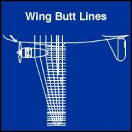
C-47 Wing Butt Lines (Start
at FBL 142.000)
|
||||||||||||||||||||||||||||
 |
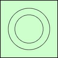
Due to the scale of our illustration we will simplify it by eliminateing the thickness of the sheet metal and any protrusions that would become invisible (folds on ribs and L bends and Z-bars for the stringers) Begin with the last rib at STA 749.00. Based on the info I have this rib is round and 22 inches in diameter. Create a circle on Layer 1 that is about 0.44 inches (our scale is 0.24 inch = 12 inches therefor each inch is 0.02. 22 inches X 0.02 = 0.44). Use the property bar to correct the dimension. Next create the cutout. The rib is 3 1/2 inches wide so the math goes like this 3.50 X 2 = 7.00, 22 – 7.00 = 15.00, 15.00 x 0.02 = 0.3 inches. Duplicate the original circle and use the property bar to correct the dimension to 0.3. | ||||||||||||||||||||||||||||
 |
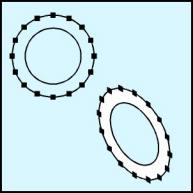
We will need more nodes on the larger circle than exist now. Select the larger circle and convert to curves (Ctrl+Q). Marquee select the nodes with the node edit tool (F10) and hit the plus sign on the Node Edit Roll-up twice. You now have 16 nodes, which exactly correspond to the stringers in this portion of the aircraft. Marquee select both circles and use the align command (Ctrl+A) to center them horizontally and vertically. Next use the combine command (Ctrl+L) and fill the result with white. The IsoEval or Isometric Menu can now be activated and a Front transformation applied. |
Home,
About, Contact,
FAQ, Shop,
Products, Services,
Learn, Tips
and Tricks, Tools
© 1997 - 2001 John M. Morris