|
|
|
|
|
|
|
|
|
|
|
|
|
||
|
|
|
|
|
|
|
|
|
|
|||||
|
|
|
||||||||||||
|
|
|
|
|
|
|
||||||||
|
|
|
|
|
|
|
|
|
|
|
|
|
||
|
|
|
|
|
|
|
|
|
|
|||||
|
|
|
||||||||||||
|
|
|
|
|
|
|
||||||||
| Isometric Angles - page 5 |
 |
Marquee select both objects and align them as shown by turning on Snap to Objects and dragging the lower angle until it snaps to the lower right corner of the main angle. Now nudge it up with the arrow key until it looks right. Make sure everything has been separated and un-grouped. Weld the outside faces of both angles with the Shaping Roll-Up. Use the Node Edit Tool (F10) to select the lower/front object and modify the upper nodes as shown in the detail. From the Shaping Roll-Up trim this shape from the main angle. |
 |
The completed compound angle. |
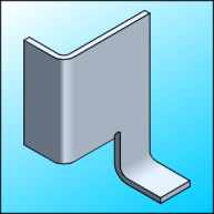 To
render: All fills will begin with C10 and M5. Adjust the K
setting after selecting the cyan and magenta colors. Select the top and
apply a Uniform Fill (Shift+F11) with these settings K0. Select the
small face of the lower tab and apply a Uniform Fill (Shift+F11) with
these settings K25. Select the front of the lower tab and apply a
Uniform Fill (Shift+F11) with these settings K50. Select the large face
and copy it to the clipboard (Crtl+C). With this face still selected
switch to the Node Edit Tool (F10) and break the node - top - third from
the left side AND - bottom - third from the left side. Break apart the
curve (Ctrl+K). Click off and then select the left side and connect the
open nodes with the Straight Line Pencil Tool. Apply a Fountain Fill
(F11) with these settings: Linear, Custom, Position 0 = K50; Position 70
= K50; Position 80 = K10; Position 100 = K25. Apply no outline. Click
off and then select the right side and connect the open nodes with the
Straight Line Pencil Tool. Click on the left side again an activate the
Fountain Fill Dialog (F11) and click OK. Select the right side again and
repeat the fill (Ctrl+R). Modify this fill by activation the Fountain
Fill Dialog (F11) and change the Angle to -60, modify the K settings at
each position as follows 0 = K25, 70 = K25, 80 = K0, 100 = K0. Apply no
outline. Now paste (Ctrl+V) the contents of the clipboard back and
change the fill to none. Finish by selecting the top with the Pick Tool
and bring it to the front (Shift+Page Up). To
render: All fills will begin with C10 and M5. Adjust the K
setting after selecting the cyan and magenta colors. Select the top and
apply a Uniform Fill (Shift+F11) with these settings K0. Select the
small face of the lower tab and apply a Uniform Fill (Shift+F11) with
these settings K25. Select the front of the lower tab and apply a
Uniform Fill (Shift+F11) with these settings K50. Select the large face
and copy it to the clipboard (Crtl+C). With this face still selected
switch to the Node Edit Tool (F10) and break the node - top - third from
the left side AND - bottom - third from the left side. Break apart the
curve (Ctrl+K). Click off and then select the left side and connect the
open nodes with the Straight Line Pencil Tool. Apply a Fountain Fill
(F11) with these settings: Linear, Custom, Position 0 = K50; Position 70
= K50; Position 80 = K10; Position 100 = K25. Apply no outline. Click
off and then select the right side and connect the open nodes with the
Straight Line Pencil Tool. Click on the left side again an activate the
Fountain Fill Dialog (F11) and click OK. Select the right side again and
repeat the fill (Ctrl+R). Modify this fill by activation the Fountain
Fill Dialog (F11) and change the Angle to -60, modify the K settings at
each position as follows 0 = K25, 70 = K25, 80 = K0, 100 = K0. Apply no
outline. Now paste (Ctrl+V) the contents of the clipboard back and
change the fill to none. Finish by selecting the top with the Pick Tool
and bring it to the front (Shift+Page Up). |
|
Home,
About, Contact,
FAQ, Shop,
Products, Services,
Learn, Tips
and Tricks, Tools
© 1997 - 2001 John M. Morris

