|
|
|
|
|
|
|
|
|
|
|
|
|
||
|
|
|
|
|||||||||||
|
|
|
||||||||||||
|
|
|||||||||||||
|
Isometric Ellipse Lesson - page 1 |
 |
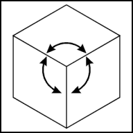
This lesson is in response to visitors requests. First, a definition. Isometric means equal measure - any projection where the angles are equal fits the definition. Those familiar with CAD drawings have seen "Isometric Projections" that contain bizarre ellipses and angles that do not fit the modern definition. Since the fifties isometric projection has come to mean that surfaces of a cube would be projected equally and would have angles with each other of 120 degrees. If you were to do the math to develop an ellipse proper for that cube you would find the answer to be 35 degrees 16 minutes rotating 120 degree increments. |
 |
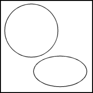
The Isometric Ellipse: Create a perfect circle about 2" in diameter by selecting the ellipse tool (F7) and constraining (Ctrl) it while watching the status line. Duplicate the circle (Ctrl+D) and move it off to the side. Create an isometric ellipse by applying a vertical scale of 57.4% from the Transform Roll-Up to the circle. |
 |
No drawing here.
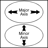
Understanding an isometric ellipse requires the definition of itís parts. The distance across the largest dimension is known as the major axis. This axis would be used to find the outside of a cylinder. The distance across the smallest dimension is known as the minor axis. This axis doubles as the isometric thrust line or the line along which parts would explode. |
Home,
About, Contact,
FAQ, Shop,
Products, Services,
Learn, Tips
and Tricks, Tools
© 1997 - 2001 John M. Morris