|
|
|
|
|
|
|
|
|
|
|
|
|
||
|
|
|
|
|||||||||||
|
|
|
||||||||||||
|
|
|||||||||||||
| Using the Intersection Command - page 8 |
 |
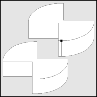
If I applied an extrusion now an extra line will appear. Use the Node Edit Tool (F10) and Node Edit Roll-Up to smooth that [highlighted in black] node. Use the Extrude Tool (Ctrl+E) to apply an extrusion with the following settings: back parallel, VP locked to object, object center, Horizontal 0, Vertical -1. 0. If the result is too deep or shallow adjust the vertical dimension until it looks right. |
 |
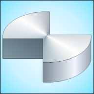
To render: Separate the Extrude
Group and un-group it. All fills will be Fountain Fill
(F11). Select the top with the Pick Tool and apply the
following settings: Conical, Angle 60, Custom, Position 0
= C15, M5, K30; Position 50 = white; Position 100 = C10,
M5, K35. Select the flat side and apply: Linear, Angle
60, From = C10, M5, K25; To = C10, M5, K55. Select the
curved side and apply: Linear, Custom, Position 0 = C10,
M5, K40; Position 65 = C5, M3; Position 100 = C10, M5,
K30.
|
 |
Purchase
our Tech Drawing Tools and work more efficiently Find the most expensive software for producing Isometric Drawings and Iíll send you a copy of Isometric Tools for free. Post your suggestion on our Contact page. Be sure to include enough information so we can verify the price. Next month you will explore how to use paper engineering data to draw directly on the computer. A free symbol library will be included. |
Home,
About, Contact,
FAQ, Shop,
Products, Services,
Learn, Tips
and Tricks, Tools
© 1997 - 2001 John M. Morris