|
|
|
|
|
|
|
|
|
|
|
|
|
||
|
|
|
|
|||||||||||
|
|
|
||||||||||||
|
|
|||||||||||||
| Completing the Aircraft Illustration - page 3 |
 |
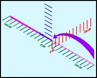
Since we have two 0 starts (Fuselage and Wing) the green grid simply runs from 0 to 480 and we need more for the extra section. Pick up the line (with the pick tool) and move the 142 end back to zero. |
 |
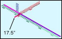
Draw the next segment from the 142.00 end (at 0.00) to about 413.00 (Purple line). Draw a crossing line back along the front to rear axis at 17.9. This is where the first angled rib on the dihedral sits. As we create this spar dupe all of the lines and set aside for the right wing. |
 |
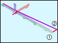
If we deduct the Point 2 Station lines from the Point 3 Station you will find that it is 44.5 inches aft of its current position. Use the Station Grid (Red Grid) to create a line that long. Snap the forward node (1) to the Point 3 end and use the Node Edit Tool to move the Point 3 end to Station 330.0 (2). |
Home,
About, Contact,
FAQ, Shop,
Products, Services,
Learn, Tips
and Tricks, Tools
© 1997 - 2001 John M. Morris