 |

|

|

|

|

|

|

|

|

|

|

|

|
|

|

|
|

|

|

|

|

|

|
|
|

|
|

|

|

|

|

|

|
|
Completing
the Aircraft Illustration
-
page 5
|
 |
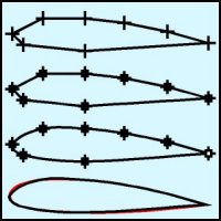
Position duplicates of this cross using the Property Bar
in the following positions:
| Position |
x-dimension |
y-dimension |
| 1 (Leading Edge) |
0.00 |
0.00 |
| 2 |
0.545 |
0.275 |
| 3 (Top of Center Spar) |
1.293 |
0.275 |
| 4 |
1.992 |
0.196 |
| 5 (Control Surface Ref) |
2.763 |
0.038 |
| 6 (Trailing Edge) |
3.494 |
-0.167 |
| 7 (Bottom of Center
Spar) |
1.293 |
-0.307 |
| 8 |
0.197 |
-0.197 |
|
 |
- Connect the "dots" by turning on Snap to Objects and
drawing a straight line (F5) from point to point.
- With the connected line selected use the Node Edit Tool (F10) to
convert it to a curve.
- Deselect the Trailing Edge node and smooth the curve.
- Clean up the result as shown by the red line behind the completed
profile.
|
 |
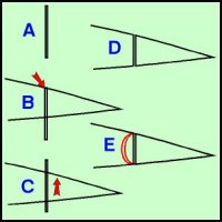
Our next step is to create the separation for the control
surface.
- Create a rectangle 0.02 wide by 0.5 high using the Rectangle Tool
and the Property Bar.
- Snap it to the # 5 node.
- Move it up 0.10 inch with the Property Bar and trim it from the
rib profile.
- Delete the rectangle.
- Convert the vertical segments to curves and use the Node Edit Tool
(F10) to modify the result as shown by the red line behind the
completed profile.
|
Home,
About, Contact,
FAQ, Shop,
Products, Services,
Learn, Tips
and Tricks, Tools
© 1997 - 2001
John M. Morris


