|
|
|
|
|
|
|
|
|
|
|
|
|
||
|
|
|
|
|||||||||||
|
|
|
||||||||||||
|
|
|||||||||||||
| Creating Cutouts in Panels - page 2 |
 |
Copy this object to a file for use in later exercises.
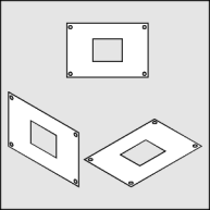
Convert to an isometric front view by
applying the following "Horizontal Scale 86.6 %, Vertical Skew -30
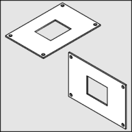
degrees". Did you know that Tech Drawing Tools can extrude along an isometric axis? Save Time - Save Money! Since it is easier to simulate depth from objects that face up apply a rotation of 240 degrees to the panel. |
 |
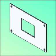
Use the Extrude Tool (Ctrl+E) to apply an extrusion with the following settings: back parallel, VP locked to object, object center, Horizontal 0, Vertical -0.05 . If there are extraneous vertical lines on your extrusion they are caused by nodes on the top that are not smooth. Use the Node Edit Tool (F10) and the Node Edit Roll-Up (Ctrl+10) to smooth the offending nodes. By rotating the result 120 degrees the panel is back on the correct isometric plane. |
 |
To render: Select the front face and choose a Uniform Fill (Shift+F11) of C20, M10. Complete the panel rendering by choosing the following lighting settings from the Extrude Roll-Up (Ctrl+E) Light 1 = front/right/top 100%, Light 2 = front/center/middle 30%. |
Home,
About, Contact,
FAQ, Shop,
Products, Services,
Learn, Tips
and Tricks, Tools
© 1997 - 2001 John M. Morris