|
|
|
|
|
|
|
|
|
|
|
|
|
||
|
|
|
|
|||||||||||
|
|
|
||||||||||||
|
|
|||||||||||||
| Creating Cutouts in Panels - page 8 |
 |
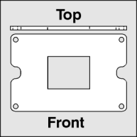
Engineering drawing of panel 5. |
 |
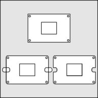
Get the object saved in exercise 1 and recreate the outside rectangle using the Rectangle Tool (F6) and Snap to Objects. Delete the original rectangle. Use the Node Edit Tool to round the corners of the rectangle with a 0.12 radius and convert to curves. Duplicate the curve and use the Node Edit Tool to marquee select/constrain/drag the outside nodes in to achieve a 0.5 wide by 0.3 high shape. Position overlapping the left side, dupe and constrain/drag to overlap the right side. Select both and combine (Ctrl+L) them. Shift click select the outside curve and Align (Ctrl+A) horizontally and vertically. Use the Shaping Roll-Up to trim the smaller curves from the outside shape. Delete the trimming object. |
 |
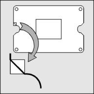
Create a square (Ctrl+F6) 0.12 wide and high. Turn on Snap to Objects and position the square at each sharp corner. [See the enlarged details] Add a node with the Node Edit Tool to the outside shape at the top intersection of the square, constrain (Ctrl) drag the corner node with the Node Edit Tool to the other intersection of the square. Select the resulting beveled line with the Node Edit Tool and convert it to a curve and then smooth. Repeat at the other three sharp corners. |
Home,
About, Contact,
FAQ, Shop,
Products, Services,
Learn, Tips
and Tricks, Tools
© 1997 - 2001 John M. Morris