|
|
|
|
|
|
|
|
|
|
|
|
|
||
|
|
|
|
|||||||||||
|
|
|
||||||||||||
|
|
|||||||||||||
| Creating Cutouts in Panels - page 7 |
 |
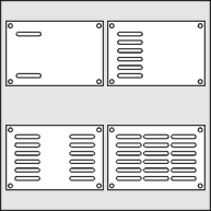
Duplicate in place and drag down using the constrain (Ctrl) key. Apply a blend with 4 steps, separate, un-group, and combine the curves. Duplicate in place and drag right using the constrain (Ctrl) key. Apply a blend with 1 step, separate, un-group, and combine the curves. Select the combined curves and the outside rectangle and Align (Ctrl+A) horizontally and vertically. Combine everything smooth all nodes and fill with white. |
 |
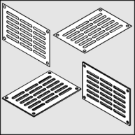
Convert to an isometric front view by applying the following "Horizontal Scale 86.6 %, Vertical Skew -30 degrees". Since it is easier to simulate depth from objects that face up apply a rotation of 240 degrees to the panel. Use the Extrude Tool (Ctrl+E) to apply an extrusion with the following settings: back parallel, VP locked to object, object center, Horizontal 0, Vertical -0.05. If the result is too deep or shallow adjust the vertical dimension until it looks right. By rotating the result 120 degrees the panel is back on the correct isometric plane. |
 |
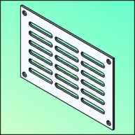
To render: Select the front face and choose a Uniform Fill (Shift+F11) of C20, M10. Complete the panel rendering by choosing the following lighting settings from the Extrude Roll-Up (Ctrl+E) Light 1 = front/right/top 100%, Light 2 = front/center/middle 30%. |
Home,
About, Contact,
FAQ, Shop,
Products, Services,
Learn, Tips
and Tricks, Tools
© 1997 - 2001 John M. Morris