|
|
|
|
|
|
|
|
|
|
|
|
|
||
|
|
|
|
|||||||||||
|
|
|
||||||||||||
|
|
|||||||||||||
| Working Efficiently 2 - page 3 |
 |
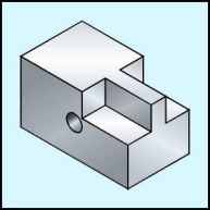
To render use the radial fill (F11) with the
following settings per face: Top; Linear, Angle 90 degrees, Edge pad 10, Custom, Position 0 C6, M3, Y0, K10; Position 50 C0, M0, Y0, K0; Position 100 C6, M3, Y0, K10. Side; Linear, Angle 60 degrees, Edge pad 15, Custom, Position 0 C6, M3, Y0, K20; Position 50 C5, M2, Y0, K5; Position 100 C6, M3, Y0, K20. Front; Linear, Angle -60 degrees, Edge pad 15, Custom, Position 0 C6, M3, Y0, K40; Position 50 C5, M2, Y0, K25; Position 100 C6, M3, Y0, K40. Hole; Linear, Angle -60 degrees, Edge pad 25, Custom, Position 0 C6, M3, Y0, K70; Position 50 C5, M2, Y0, K10; Position 100 C6, M3, Y0, K40. |
 |
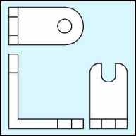
Engineering Drawing of a machined bracket. Note that there are two distinct objects. Although the base and side are joined it will be quicker to create them separately and join them later. |
 |
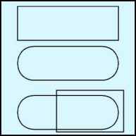
Letís create the base first. Use the rectangle tool (F6) to produce a rectangle 1" high by 3" long by watching the status line and dragging across the page. You can use the Property Bar to correct minor errors only. Next choose the Node Edit (F10) tool to completely round the ends and then convert this to curves (Ctrl+Q). Delete the double nodes at the round ends and then add a node with the + sign in the Node Edit Roll-up. Use the rectangle tool (F6) to produce a rectangle 1.25" high by 2" long by watching the status line and dragging across the page. Use the Property Bar to correct size. |
Home,
About, Contact,
FAQ, Shop,
Products, Services,
Learn, Tips
and Tricks, Tools
© 1997 - 2001 John M. Morris