|
|
|
|
|
|
|
|
|
|
|
|
|
||
|
|
|
|
|||||||||||
|
|
|
||||||||||||
|
|
|||||||||||||
| CorelDRAW verses CAD - Round 1 - page 6 |
 |
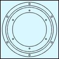
The procedure you just followed, created the holes in one position on the cylinder. If you had the engineering drawing you would find a reference to the holes being positioned 6 times at 60.0 degrees. To accomplish that, simply select the combined holes and use the Transform Roll-up to apply a 60.00 degree rotation to a duplicate twice. |
 |
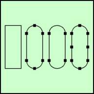
To create the cutouts choose the Rectangle Tool and create an object 0.5 inches wide by 1.331 inches high. Since you will be rounding the ends you can only use the Property Bar for minor adjustments. It will distort the roundness. Use the Node Edit to completely round the ends of the rectangle. This process produces an extra node at the center of the rounded ends that must be removed. Convert the rectangle to a curve (Ctrl+Q), Marquee select the nodes at the extents on the round ends with the Node Edit tool (F10) and delete them. Since you must have a node at the center, marquee select all of the nodes and hit the plus sign on the Node Edit Roll-up. The extra nodes along the sides won’t matter so leave them. |
 |
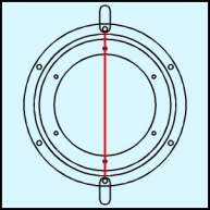
From the engineering drawing I know that the diameter of the inside of the cutout is 7.176 inches. Create a vertical straight line 7.176 inches long and apply a red outline so it stands out. Use the Property Bar to change the position to x = 0.0, y = 0.0. Next select the rounded rectangle with the pick tool and snap a round - end center node to the top of the line. Dupe and repeat for the bottom cutout. The line has served its purpose and can be deleted. |
Home,
About, Contact,
FAQ, Shop,
Products, Services,
Learn, Tips
and Tricks, Tools
© 1997 - 2001 John M. Morris