|
|
|
|
|
|
|
|
|
|
|
|
|
||
|
|
|
|
|||||||||||
|
|
|
||||||||||||
|
|
|||||||||||||
| Plotting the Rigging - page 5 |
 |
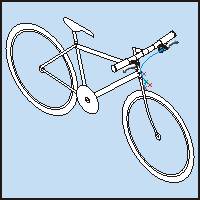
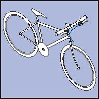
The blue plot shows the front brake cable location. The cylinder locations are shown by the red x (small) or blue x (large). The plate location is shown by the purple x. The joining disk location is indicated by the green x. Plot the blue line using the pencil tool. Convert the sections to curves and smooth. Duplicate and position the cylinders, plate and joining disk and adjust the front to rear order. |
 |
Apply a contour with the following settings to the plot: 1 step - offset 0.08. Separate, delete the plot line and fill with black. You will need to cut the contour in two to adjust the front to rear order and position the components. Trim any excess at the ends and round the end with the node edit tool. Add the v between the joining disk and the brake arms. Apply the same contour and fill etc. |
 |
Next months tutorial will cover adding the reflectors. |

Home,
About, Contact,
FAQ, Shop,
Products, Services,
Learn, Tips
and Tricks, Tools
© 1997 - 2001 John M. Morris