|
|
|
|
|
|
|
|
|
|
|
|
|
||
|
|
|
|
|||||||||||
|
|
|
||||||||||||
|
|
|||||||||||||
| Installing the Wings & Building the Engine Nacelles - page 2 |
 |
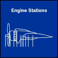
A few months back I provided the following information on
the C-47 Engine Stations.
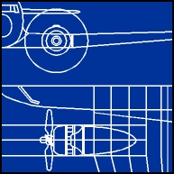
Stations run from front to back and are one of the three sets of dimensions we need. The others are that the Thrust Line (Vertical center of the engine) sits about centered on the wing Water Line and that the butt lines are 31.00 left and right. The last numbers we need are that the Prop has a radius of 69.5 inches (11.5 feet divided by 2) and sits horizontally and vertically on the thrust line at Station 103.00. |
||||||||||||||||||||||||||||||||||||||||||
 |
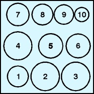
There are ribs at each Station Line and the Diameters can
be seen in the table below:
|
||||||||||||||||||||||||||||||||||||||||||
 |
From the Taper end forward create in turn the 10 ribs (Our Dia.) you need by drawing a circle (constrain (Ctrl)). Convert the first circle to a curve (Ctrl+Q) and use the Node Edit Tool to add nodes. Use the Property Bar to correct the dimensions of each rib (Duplicate the ribs as you go) but be sure to work from back to front. |
Home,
About, Contact,
FAQ, Shop,
Products, Services,
Learn, Tips
and Tricks, Tools
© 1997 - 2001 John M. Morris