|
|
|
|
|
|
|
|
|
|
|
|
|
||
|
|
|
|
|||||||||||
|
|
|
||||||||||||
|
|
|||||||||||||
| Creating Extrusions - page 8 |
 |
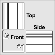
Engineering drawing of a corner extrusion with gasket tabs. |
 |
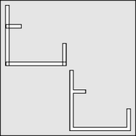
Draw a rectangle (F6) about 0.11 inch wide by 2 inches high. Rotate a duplicate 90 degrees and reduce the horizontal dimension to 0.5 inch long and position as shown by the upper tab. Duplicate this tab and adjust the horizontal dimension to 1.8 inches long and Align (Ctrl+A) Horizontal - left, Vertical - bottom. Duplicate the vertical rectangle, Align (Ctrl+A) Horizontal - right, Vertical - bottom and adjust the height to 0.66 high. Finally use the Shape Roll-Up to weld everything together. Activate the Node Edit Tool (F10) and delete any extra nodes, then marquee select all nodes and convert to straight lines. |
 |
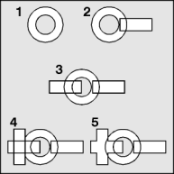
To create the gasket tabs create a circle (F7+Ctrl) 0.5 inch in diameter. [1] Apply a Horizontal and Vertical Scale of 55 percent to a duplicate, marquee select both circles and combine (Ctrl+L) them. [2] Create a rectangle (F6) as shown and Align (Ctrl+A) vertically. [3] Repeat the last step creating a slightly larger rectangle. [4] Use the Transform Roll-Up to apply a 90 degree rotation to a duplicate of the step 3 rectangle. [5] Weld those two rectangles together. |
Home,
About, Contact,
FAQ, Shop,
Products, Services,
Learn, Tips
and Tricks, Tools
© 1997 - 2001 John M. Morris