|
|
|
|
|
|
|
|
|
|
|
|
|
||
|
|
|
|
|||||||||||
|
|
|
||||||||||||
|
|
|||||||||||||
| Using CAD Data to produce isometrics - page 2 |
 |
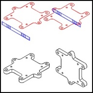
Open the engineering drawing baseplt4.cdr [If we were actually using CAD data a DXF import would be used]. Open the Layers Roll-Up, make the Front layer active and select the object on that layer [red] and fill with white. Convert this object into a front view isometric by using the Transform Roll-Up to apply the following: (Horizontal scale 86.6%, Skew vertical -30.0 degrees). Select the object on the Side [blue] layer and convert this object into a side view isometric by using the Transform Roll-Up to apply the following: (Horizontal scale 86.6%, Skew vertical 30.0 degrees). |
 |
Select both of the converted objects and use the Transform Roll-Up to apply a 240 degree rotation to create a view looking down. Align (Ctrl+A) horizontally and vertically. Zoom in (F2 marquee) on the closest corner and fine turn the alignment so the depth can be confirmed. Use the Extrude Roll-Up to apply the following to the front [red] object: Back Parallel, VP Locked to Object, Object Center, Horizontal 0.0, Vertical -0.58. Move the extrusion to layer 1 and add the two missing lines then delete the Front, Side, and Top layers. Marquee select everything, group (Ctrl+G) and use the Transform Roll-Up to apply a 120 degree rotation. Bet you thought this was going to be hard! |
 |
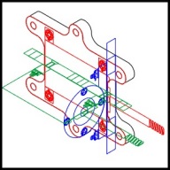
Copy (Ctrl+C) the base plate to the clipboard and open the data file motor4.cdr. Typically CAD assembly drawings do not contain the kind of data that would allow using the components directly. This happens because assemblies often contain vendor parts for which real data is not available. However, it is still easy to produce an isometric. Make Layer 1 active and paste (Ctrl+V) the base plate into the drawing and move off to the side. Convert each of the layers/faces into isometrics by using the Transform Roll-Up to apply the following: Front [red] - (Horizontal scale 86.6%, Skew vertical -30.0 degrees). Side [blue] - (Horizontal scale 86.6%, Skew vertical 30.0 degrees). Top [green] - (Vertical scale 86.6%, Skew horizontal -30 degrees, Rotate -30 degrees). Line up the three faces as shown. Turn on Snap to Objects and carefully position the base plate pasted at the beginning of this step over the object on the front layer. At this point turn off Edit across layers or Multi Layer editing and make Layer 1 active. |
Home,
About, Contact,
FAQ, Shop,
Products, Services,
Learn, Tips
and Tricks, Tools
© 1997 - 2001 John M. Morris