|
|
|
|
|
|
|
|
|
|
|
|
|
||
|
|
|
|
|||||||||||
|
|
|
||||||||||||
|
|
|||||||||||||
| Using CAD Data to produce isometrics - page 3 |
 |
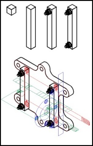
Activate the Symbol Roll-Up [star tool] and scroll down to the Lesson03 symbol font. I determined the size for symbols by matching them against one of the guide objects. Set the size at the bottom of the Roll-Up to 1.2 inches and drag symbol #33 over the right hand motor flange and align it to the top of the Front layer [red] guide. Get the node edit tool (F10) and marquee select the bottom nodes and constrain (Ctrl) drag them down to the bottom position as indicated by the Front layer [red] guide. Fill this symbol with white. Now select a symbol size of 0.8 inch and drag symbol #34 onto the screen. Fill with white, break apart (Ctrl+K) and group (Ctrl+G). Use the Transform Roll-Up to apply a 120 degree rotation and move into position. Note: Be careful the Front layer position shows the hardware without any depth, position the symbol correctly. Set your Preferences (Ctrl+J) place duplicates to Horizontal 0.0, Vertical 0.0. Duplicate the symbol and constrain (Ctrl) drag it to the bottom position. Select all three objects, duplicate (Ctrl+D) and move to the left hand position. |
 |
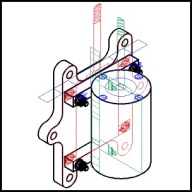
Turn on Edit across Layers or Multi layers, marquee select everything and use the Transform Roll-Up to apply a 120 degree rotation. [Rotating allows the creation of objects along a vertical axis. This is a faster and more accurate method than trying to line things up along a 30 degree axis.] Turn off Edit across Layers or Multi layers and make Layer 1 active. To determine the size of symbol #35 look at your ruler. I see that about 4 inches should be good. Change the Symbol Roll-Up to that size and drag symbol #35 onto the page and line up with the location shown on the side [blue] layer. Manually adjust the size again using the side [blue] layer. Fill with white. Use the node edit tool (F10) to constrain (Ctrl) drag the bottom nodes of the symbol down to the correct depth as indicated by the Top [green] layer. A handy feature of these symbols is that they contain nodes across the major, minor, and both isometric radials. Activate the Node Edit Tool (F10) and observe the nodes on the upper part of symbol #35. |
Home,
About, Contact,
FAQ, Shop,
Products, Services,
Learn, Tips
and Tricks, Tools
© 1997 - 2001 John M. Morris