|
|
|
|
|
|
|
|
|
|
|
|
|
||
|
|
|
|
|||||||||||
|
|
|
||||||||||||
|
|
|||||||||||||
| Using CAD Data to produce isometrics - page 6 |
 |
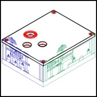
To create the top plate activate Edit Across Layers or Multi Layer. Select the isometric guide objects on the Front [red], Side [blue], and Top [green] layers and constrain (Ctrl) move way up clearing everything by a very good margin. Ungroup (Ctrl+U) the Top [green] layer and move the upper rectangle to Layer 1. Repeat with the rectangles on the Side [blue] and Front [red] layers. Add the 3 holes for the bearings to Layer 1 using the Symbol Roll-Up size 0.6 and symbol #38 using the Front [red] layer as a guide. Add the 4 screw holes to the top plate by changing the size in the Symbol Roll-Up to 0.15 and dragging symbol #40 onto the positions indicated by the screw heads shown on the Front [red] layer. Shift click select the corresponding bearing holes on the top plate and bottom plate and align (Ctrl+A) horizontally. Repeat for the screw holes on the top plate and the standoff symbols on the bottom plate. Note; only the top section is shown. |
 |
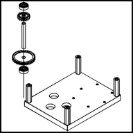
To create gear train 1. Move down to the bottom plate and locate the left bearing hole. Beginning at the center of this hole constrain (Ctrl) draw a straight line up to about 6 inches long. Working from the bottom up add the following symbols with the stated sizes: Bearing #41 0.6 inch, Helical Gear #42 1.5 inch, and Shaft #43 0.4 inch. Place the shaft over the side [blue] guide that remains in the middle of the page and correct the height using the node edit tool (F10). The shaft should extend from slightly above the top of the upper bearing to close to the bottom of the bottom plate. Move this symbol back to the gear train 1 position. Back to adding symbols: Spur Gear #44 0.8 inch, Bearing #41 0.6 inch. Now adjust the vertical between the symbols to about one eight inch. Make sure nothing overlaps. This gear train is going to get in the way later so it must be moved. Shift click the gear train 1 symbols and the line and move them left of the left standoff and align (Ctrl+A) horizontally. |
 |
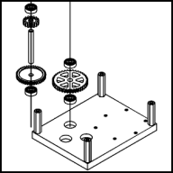
To create gear train 2. Move to the middle bearing hole and draw another 6 inch vertical line positioned from the center of the hole and up. Add the following symbols with the stated sizes: Bearing #41 0.6 inch, Spur Gear #45 1.8 inch, and another Bearing #41 0.6 inch. Adjust the vertical spacing again. Shift click everything on this gear train ending with the bearing hole and align (Ctrl+A) horizontally. |
Home,
About, Contact,
FAQ, Shop,
Products, Services,
Learn, Tips
and Tricks, Tools
© 1997 - 2001 John M. Morris