|
|
|
|
|
|
|
|
|
|
|
|
|
||
|
|
|
|
|||||||||||
|
|
|
||||||||||||
|
|
|||||||||||||
| Using CAD Data to produce isometrics - page 7 |
 |
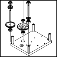
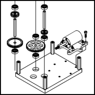
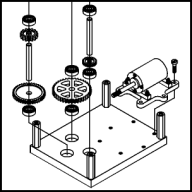
To create gear train 3. Move to the right bearing hole and draw another 6 inch vertical line positioned from the center of the hole and up. Add the following symbols with the stated sizes: Bearing #41 0.6 inch, Helical Gear #46 0.65 inch. Now duplicate the gear train 1 shaft and bring it over. Duplicate the Bearing #41 symbol and move it to the top of this gear train. Adjust the vertical spacing again. Shift click everything on this gear train ending with the bearing hole and align (Ctrl+A) horizontally. |
 |
To explode the motor move it into the offset position shown. Draw a vertical guideline from the center of the far right motor mounting hole down about 1 inch. Now draw a vertical line from the corresponding hole on the bottom plate up to between the standoff and the motor base plate. Continue with a line segment holding the constrain (Ctrl) key to 30 degrees [watch the status line] to the guideline and click end. Add another segment up to the bottom of the motor base plate. Move the guideline up so that the bottom of the line is centered in the motor mounting hole and use the Symbol Roll-Up to add the Slot Head Screw #48 symbol with a size of 0.5 inch. |
 |
Back to the gear train 1 bearing hole. Draw a vertical line from the center of this hole up 0.4 inch, over 1.7 inch at 150 degrees. Now shift click everything on gear train 1, turn on Snap to Objects and position the 6 inch vertical line at the end of the line just completed. |
Home,
About, Contact,
FAQ, Shop,
Products, Services,
Learn, Tips
and Tricks, Tools
© 1997 - 2001 John M. Morris